A typical LTE frame is 10 ms (milliseconds) long. Each LTE frame has 10 sub-frames (1 ms each) while each sub-frame is further divided into 2 slots (0.5 ms each). The slots are divided into symbols – each slot has either 6 or 7 symbols. The number of symbols per slot depends on the size of the cyclic prefix. The LTE uses 2 CP sizes – Normal CP (4.67 µs) and Extended CP (16.67 µs). In general configuration and LTE deployments for urban areas, the Normal CP is used so the number of symbols per slot would be 7. The symbol time (Ts) for each LTE symbol is 66.67 us (much shorter than the symbol time for 10 MHz WiMAX symbol). Adding Cyclic Prefix to Ts makes it around 71.34 us. The spacing between two carriers is constant and is equal to 15 kHz (in most of the cases).
Resource Elements and Resource Blocks
Each symbol on a carrier is called a Resource Element, thus, we can say that LTE frame is made up of Resource Elements. A group of 7 resource elements in time axis and 12 resource elements in frequency axis make up a Resource Block (RB) and each RB spans over 180 kHz. Resources or bandwidth is allocated on the basis of RBs. The Scheduler tells each UE (user or mobile) about the number of RBs allocated to it.
Resource Element Group (REG)
For control channels, another couple of groupings are made as the control channels cannot span over a full RB. REG is made up of a group of 4 REs and is used for control channels – PCFICH, PHICH, and PDCCH.
Control Channel Element (CCE)
1 CCE is equivalent to 9 REGs or 36 REs. PDCCH aggregation layers use CCEs to define each layer. Details of REGs and CCEs will be explained in the next topic.
LTE Physical Channels
LTE PHY Channels – Downlink
PCFICH (Physical Control Format Indicator Channel)
This is the Physical Control Format Indicator Channel and describes the format of the PDCCH. PCFICH exists in the first OFDM symbol and spans over 16 REs which is equivalent to 4 REGs (Resource Element Group – 1 REG = 4 REs). If CFI (Control Format Indicator) is 1 then only the first OFDM symbol is used for PDCCH, if CFI is 2, then first 2 OFDM symbols are used and if the CFI is 3 then the first 3 OFDM symbols are used for PDCCH. A common misconception is that the PCFICH is placed in the first OFDM symbol clustered together while actually, the each REG of the PCFICH is evenly distributed across the whole BW. This permutation is defined by the PCI (Physical Cell ID).
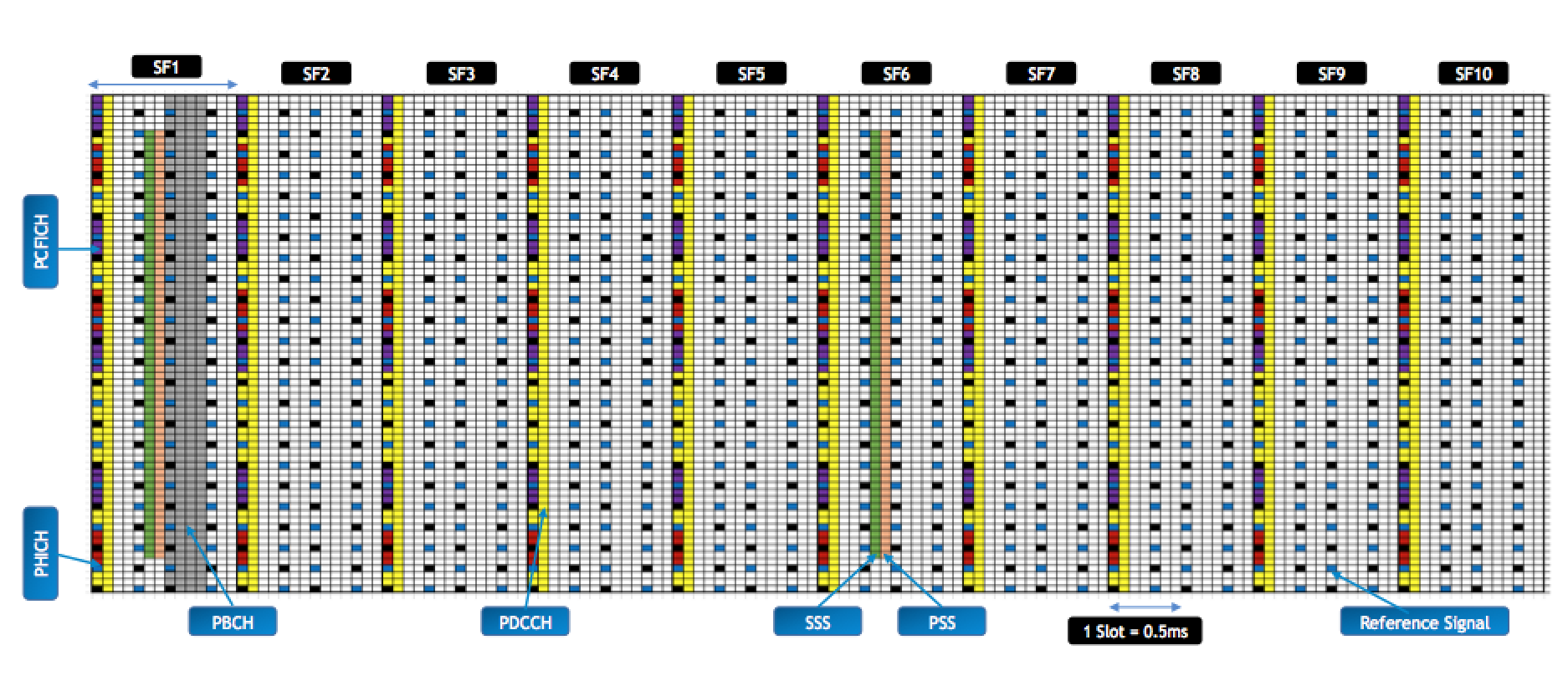
PHICH (Physical HARQ Indicator Channel)
This is the Physical HARQ Indicator Channel which carries the HARQ ACKs and NACKs for the UE’s Uplink data traffic – ACKs/NACKs for uplink data has to be sent in DL by this channel. PHICH is placed in the first OFDM symbol of the sub-frame. Each PHICH consists of 3 REGs (12 REs) and multiple PHICHs can use the same set of REGs known as PHICH groups. This is made possible by using orthogonal sequences (much like CDMA) and PHICH uses a total of 8 orthogonal sequences. The number of PHICHs supported per sub-frame depends on the total number of orthogonal sequences and the PHICH group multiplier (parameter Ng). Consider that the PHICH group multiplier (Ng) is set to 1 which is equivalent to 7 PHICH groups (10 MHz – 50 RBs) then the number of PHICHs supported would be 7 (PHICH Groups) x 8 (Number of Orthogonal Sequences) = 56 PHICHs. The total number of REs would be 7 PHICH groups x 3 REGs per PHICH group x 4 REs per REG = 84 REs.
PDCCH (Physical Downlink Control Channel)
This is the Physical Downlink Control Channel and typically contains the following information
- UE C-RNTI: It is the Cell Radio Network Temporary Identity and it is required to identify the UE. This ID is unique within a cell and PDCCH is scrambled using the PCI and the C-RNTI.
- DL Resource Allocation: It also contains the starting point of RBs and the number of RBs allocated to the UE. The UE goes to the starting RB and reads the number of RBs specified in PDCCH.
- MCS: It also indicates the MCS used for downlink direction. UEs in good RF conditions are granted better MCS (e.g 64QAM) than the ones in poor RF conditions.
- UL Grants: It also contains information of UL grants and resource allocations.
- Transmit Power Command: TPC is used to adjust UL power of the UE. The UEs near the eNB need to transmit at lower powers so that they do not over-shadow the UEs at the cell edge. Similarly, the UEs at cell edge may need to increase their power in order to be decoded at the eNB but the power needs to be adjusted in order to reduce the interference on the other eNBs. TPC is sent in PDCCH for all the PUCCH (UL Control Channel) and PUSCH (UL Shared Channel).
PDCCH Aggregation Layers
PDCCH exists on either the 1st symbol or the 1st two symbols or the 1st three symbols depending on the information in PCFICH. There are 4 aggregation layers for the PDCCH and the difference is in the number of CCEs.
- PDCCH aggregation level 1, it consists of 1 CCE (9 REGs or 36 REs)
- PDCCH aggregation level 2, it consists of 2 CCEs (18 REGs)
- PDCCH aggregation level 3, it consists of 4 CCEs (36 REGs)
- PDCCH aggregation level 4, it consists of 8 CCEs (72 REGs)
The aggregation levels might be explained with help of an example. Consider a UE-A at cell edge with poor RF conditions and a UE-B at good RF conditions near the eNB. The UE-B does not need the PDCCH to be coded with extensive FEC (may use 2/3 or 3/4) and repetitions as it is in good RF conditions but the UE-A would need extensive FEC (1/6 or 1/12) and repetitions (rep 4 or rep 6). So, the UE-B PDCCH (FEC of 2/3 or 3/4 and lower repetitions) would use a lower aggregation level while the UE-A PDCCH (FEC of 1/6 or 1/12 and higher repetitions) would use a higher aggregation level.
Similarly, the PDCCH for control message allocation may use higher aggregation level while the PDCCH for some data message resource allocation may use a lower aggregation level
Note: PDCCH may consist of 1st four OFDM symbols for 1.4 MHz BW due to smaller number of carriers, an addition might be required in the number of symbols to transmit the whole control information successfully.
PBCH (Physical Broadcast Channel)
This is the Physical Broadcast Channel and contains the MIB for the LTE network. The PBCH takes 72 subcarriers into 4 symbols around the DC sub-carrier in the second slot of the first sub-frame. It re-occurs once every frame and the whole MIB is delivered in 4 consecutive transmissions in 4 consecutive frames. Since, each LTE frame is 10 ms long so the PBCH takes 40 ms to complete it. It contains the DL BW, PHICH configuration and the system frame number.
A common query is why the PBCH contains the PHICH configuration. PBCH is to be decoded in the beginning so the UE would not be expecting any HARQ ACKs/NACKs so why should PBCH transmit PHICH configuration. The UE needs to know the PDCCH location in the 1st OFDM symbol and to de-interleave the 1st OFDM symbol, it needs to know the locations of PHICH, PCFICH and RS (Reference Signals). Now, the locations of the RS and the PCFICH are calculated by using the PCI (Physical Cell ID – calculated from the S-SS and P-SS which are decoded before the PBCH) and since the UE already knows the PCI before it starts decoding the PBCH so it knows the locations of the RS and the PCFICH. However, it still needs to know the locations of the PHICH groups so that has to be transmitted in the PBCH. Once, the UE has the knowledge about the PHICH, PCFICH and RS locations then it knows that the remaining REs belong to PDCCH.
Note: It is a common misconception that the MIB has a parameter for the number of transmit antennas which is not correct. The MIB has a CRC however, which is scrambled with one of three sequences which maps to the number of antennas used in the cell. So, when the UE calculates the CRC from the decoded MIB it compares against each of the three descrambled CRCs looking for a match and hence discovers the number of antennas.
S-SS (Secondary Synchronization Signal) and P-SS (Primary Synchronization Signal):
These signals are used by the UE for synchronization reasons. The synchronization signals are transmitted once every 5 ms. The PSS is sent on the last symbol (7th OFDM symbol) of slot 0 and slot 10 while SSS is sent on the second last symbol (6th OFDM symbol) of slot 0 and slot 10. They use 72 sub-carriers in total, centered on the DC sub-carrier.
Introduction to Physical Cell ID
The PSS is supposed to provide synchronization with symbol timing and knowledge about carrier frequency while the SSS is supposed to provide frame timing synchronization and knowledge about CP configuration. The PSS and SSS combine together to form the PCI. SSS contains the Physical Channel ID Groups which ranges from 0 to 167 while the PSS contains the Physical Layer ID which ranges from 0 to 2. Together, they form 504 possible sequences known as the Physical Cell ID (PCI) which is used to scramble the channels in the cell.
Note: There is a mismatch in different documents on the number of carriers assigned to PSS and SSS. Some authors write that 72 sub-carriers are used while others say that 62 sub-carriers are used. Actually, 62 sub-carriers are assigned to the PSS and SSS while there is a guard-band of 5 sub-carriers on both sides and thus the total number of sub-carriers consumed is equal to 72. So, both the answers can be assumed correct.
PDSCH (Physical Downlink Shared Channel)
This is the Physical Downlink Shared Channel which contains the Downlink traffic or data for the UEs. Each downlink allocation on the PDCCH points to a resource on PDSCH. It also carries SIB and Paging messages.
Downlink Reference Signals
Reference signals or symbols are used for channel estimation. They serve the same purpose that the Pilot signals do in other technologies. The location of the reference symbols is fixed along the time axis as they exist on the 1st and 5th symbol of every slot. Each Reference symbol takes one RE and the total number of REs in either the 1st or the 5th symbol depends on the bandwidth as there are 4 Reference Symbols per RB so it means that within each RB, there would be 2 RS in the 1st OFDM symbol and 2 RS in the 5th OFDM symbol. The position of the RS in the frequency domain varies on the basis of the PCI. The distribution of the RS in time and frequency domains helps the UEs to estimate the channel conditions in both time and frequency.
In case of 2 antenna system, an important thing to remember is that the RS position along the frequency axis varies for each antenna. The UE needs to perform channel estimation for both the antennas as the channel conditions might vary depending upon the antenna spacing, so the RS locations on the frequency axis is changed for each antenna. The RS sent by one antenna would be DTX for the other antenna (Discontinuous Transmission) which means there would be no transmission on that symbol for the other antenna. It is important to note that the RS location with respect to the time axis always remains fixed.
If you have any questions or feedback, simply drop a comment below and I will surely get back to you. Also, if this has been helpful, then please subscribe to our Youtube channel – Our Technology Planet for more exciting stuff and videos.
Ali Khalid
Latest posts by Ali Khalid (see all)
- 5G Coverage Expansion Analysis – Find The Optimal 5G Coverage Threshold For Your Network - November 9, 2024
- 5G Coverage Expansion - November 9, 2024
- 5G SA Cell Search & Network Entry Matrix - July 18, 2023
Impressive posts! My blog UY5 about Thai-Massage also has a lot of exclusive content I created myself, I am sure you won’t leave empty-handed if you drop by my page.
so, 1 symbol not equal to 1 RE ???
No
Dear Ali, Thanks for the Article well explained.
Can you pl help for more explanation on PHICH Group, Bandwidth wise Like we have 10 Mhz -7 PHICH Group and on Parameter Ng
Hello Rajiv,
Please follow the link below and post your question in Youtube comments section and Ali Khalid will be able to answer. Thanks
https://youtu.be/nyzHkIpWFjE
Hi Ali Bhai very well explained easy to understand many thanks for sharing your knowledge with us
have a good day bhai
Regards
Tajinder Singh
Thanks Tajinder
Ali bhai your articles are truly amazing really appreciate your hard work brother.
Thanks 🙂
Its really helpful article. Very easily and well described. Thank you for such nice article.
Salute my friend
You are welcome 🙂
Thank you dear, It helped me a lot when i am trying to teach to other people around
Thanks a lot Ali Khalid. You have explained in very easy words to understand the things.
You are welcome, Shyam.
Khalid ji,
First of all brilliant explanation !!!
I need to know how 504 PCIs come in the picture !!
Any logic behind this “magic” number ?
Thanks a lot Eng.Ali Khalid for a perfect explanation ?
Thanks Khalid Ji for your explanation
Great explanations
Appreciate your efforts, Thanks eng.ALi
God bless you
Thanks Ahmed 🙂
Can you write something similar on UL Frame Structure covering each channel
Thank you sir, a very nice explanation
Thanks Ali good explanation;
i have one question about the aggregation level as in Huawei we have PDCCHMAXCODERATE from 75 to 120.
What will be the impact if we will increase the code rate.
Hi Sufyan, I explained that in the LTE throughput optimization article.
Dear
It not only pleasure to read your explaination but also to read your answers to all questions.
I have a question:
If i respect PCI between cell (No collision or confusion) so the position of RS will be respected and then the UE can decode “without error” the RS by scrambling with the PCI and then make channel estimation.
Why so there is interference in LTE ?
What i know that the interference in RS signal makes interference in LTE DL.
The location of RS for cell-1 will be used by PDCCH or PDSCH of cell-2. So, these signals on PDSCH and PDCCH can increase the background noise even though they have a different structure. However, in case of RS to RS overlap between two cells (mod3 scenario), the impact is higher as they have same structure and the RS are always present so the interference impact is permanent while the PDCCH/PDSCH are load dependant so their interference impact is not permanent. This is why the CQI goes down in busy hours since the aggregate noise on PDCCH/PDSCH increases.
Thanks.
is there Cell Breathing in LTE ?
could you please elaborate.
BR
Simply put, cell breathing in 3G is due to the fact that all users have same frequency resource with a different code. But in LTE, the users have different frequency allocations (RBs) so we can say that cell breathing is not present in a literal sense of the word. However, once the load in the area increases, that will increase interference from neighboring cells and reduce SINR. That can cause reduction in cell edge rates and even drops. However, most of the networks use RSRP for the mobility decisions and with increase in interference, the SINR is impacted while the RSRP does not show a similar degradation. So, if UEs are using RSRQ as the mobility indicator then it is possible to shrink cell coverage as UEs will leave the serving cell when the interference is high – for instance in busy hours.
Thanks.
So what’s the benefits of using RSRQ (with RSRP or alone) in mobility ?
Because Nokia has a feature for RSRQ based mobility.
This is going to be a lengthy answer. I am planning to write short articles based on some of the questions that I have received. So, I will add the RSRP, SINR, RSSI and RSRQ details in that along with their use cases.
Dear
You said in BH the CQI goes down.
Does CQI and allocation of PDSCH is based on SINR of RS or SINR of PDSCH ?
thanks.
UE uses RS to for all channel estimation decisions
Thanks Ali, quite concise and straight to the point.
DL Resource Allocation: It also contains the starting point of RBs and the number of RBs allocated to the UE. The UE goes to the starting RB and reads the number of RBs specified in PDCCH.
regarding DL Resurce Allocation, I just captured the physical signal but how can I (the reciever) decode this signal?can you explain more? Thanks again Ali
The RNTI of the UE is used to decode the channels. In order to actually see the Resource Allocation, tools are required that can decode it for you. Usually vendors have such tools but most of the drive test tools do not show the messages at this layer. You may use Qualcomm’s QXDM which might provide you with useful insights.
Thanks alot Ali
“This is made possible by using orthogonal sequences (much like CDMA) and PHICH uses a total of 8 orthogonal sequences. The number of PHICHs supported per sub-frame depends on the total number of orthogonal sequences and the PHICH group multiplier (parameter Ng). Consider that the PHICH group multiplier (Ng) is set to 1 which is equivalent to 7 PHICH groups (10 MHz – 50 RBs) then the number of PHICHs supported would be 7 (PHICH Groups) x 8 (Number of Orthogonal Sequences) = 56 PHICHs. The total number of REs would be 7 PHICH groups x 3 REGs per PHICH group x 4 REs per REG = 84 REs.”
Why isnt 7 PHICH groups x 8 Orthogonal Sequences x 3 REGs per PHICH group x 4 REs per REG
These are two different things. 1 PHICH group can support 8 users so 7 PHICH groups can support 56 users. While each PHICH group consists of 3 REGs and each REG consists of 4 REs – this means that 7 PHICH groups will take 84 REs.
Thanks , i got it now.
You are doing a great job. Such acts are rare these days , thanks again 🙂
thank you very much Mr Ali
can you please share what is the maximum supported PHICH group ?
Good knowledge sharing articles posted by you,Thank You
Keep Sharing with details analysis including parameter tuning
Thanks Shailesh 🙂
It is always with pleasure that I read your documents, thanks for the sharing and thanks for your time.
Thanks, there are more to come 🙂
The position of RS in frequency axis depends on PCI as u stated…. And for 2/3/4 Antenna system it also varies along frequency domain… while pci remain same. Can u please explain in detail… thanks
The change in position of RS with PCI is explained in my PCI Planning Article (link given below)
http://ourtechplanet.com/pci-planning-facts-myths
Very good explanation of LTE concepts, thanks a lot Ali for share it.
Best explanation for all LTE physical channels. Thanks for sharing.
PDCCH Aggregation Layers :- Could you please explain deciding factors for different aggregation level based on UE condition? It will help to improve PDCCH capacity issues in live network.
The basic deciding factor for the PDCCH aggregation layer change is BLER. Based on this, vendors have maximum threshold of coding rates for the PDCCH and if the scheduler determines that the maximum coding rate has been reached so it will shift to the higher aggregation layer in order to conserve the BLER target for the PDCCH. In simple words, it means that the users in bad coverage need more robustness so they will be using Agg Layer 8 while users in good coverage may be using Agg Layer 2.
As BLER is measured at Enode B based on HARQ for DL which is based on PDSCH decoding by UE, is it right approach to use bler for deciding PDCCH aggregation level rather than CQI which is better indicator of UE RF condition ?
Both CQI and BLER are used together for the allocations. CQI is more of an inner loop while BLER works as a outer loop.
With regard to the uplink, and this may vary with different LTE versions, but which ones are not using Listen Before Talk? And if they are not using LBT, then what is the collision detection/resolution mechanism? Finally, the big question: On a loaded LTE network, what percentage of the physical bandwidth is lost to overhead?
I am planning to write an article on Uplink structure as well. So, I will add the overhead calculation as well 🙂
Dear Ali Bhai,
Thanks for sharing such a marvelous explained articles . I’m waiting for your next article. Please keep on sharing.
You are welcome
Hi Ali,
Has this been written already?
Am not able to find it. It would be really helpful if you can write an article regarding the uplink structure including all the channels, preamble calculation, etc..,
Not yet, soon 🙂
سلام علیک شکرا علی احسنت
very good explanation .
Thanks, Reza.
Great Illustration
Thank you, Abdullah.