
In order to understand LTE network entry steps, we must have knowledge of physical channels which you can get from my article “LTE Frame Structure Made Simple“.
The first thing UE needs to do is to search for Primary Synchronization Signal (PSS). The location of PSS is in the 1st and 6th subframe of LTE and within the subframe it exists on the last symbol of the slot. So, once the UE has decoded the PSS, it gets the following information.
- PSS gives the slot boundary timing independant of the CP length, so syncs at slot level.
- It provides the center frequency as it is around the DC carrier.
After this, the UE starts looking for the Secondary Synchronization Signal (SSS) which is just one symbol before the PSS. The PSS is on the 7th symbol of the 1st slot of 1st & 6th subframe while SSS lies on the 6th symbol. After decoding SSS, the UE gets the following information.
- UE gets to know the CP length as it has the duration of two consecutive symbols (SSS and PSS) so it can derive whether the eNB is using normal CP or extended CP.
- Since the location of SSS and PSS differs in TDD and FDD so the UE can also find out the frame type.
- Next thing to find out is the start of the frame. As SSS & PSS exist in both Subframe 1 and 6, so the UE needs to know which of the frame is the 1st subframe. That is why the SSS is different in both subframes and therefore, after decoding the SSS, the UE can understand which is the 1st subframe. So, this ensures that the UE is synchronized at both frame and symbol level.
The PCI (Physical Cell Identity) is made up of a combination of PSS & SSS with the following equation
PCI = 3(SSS) + PSS
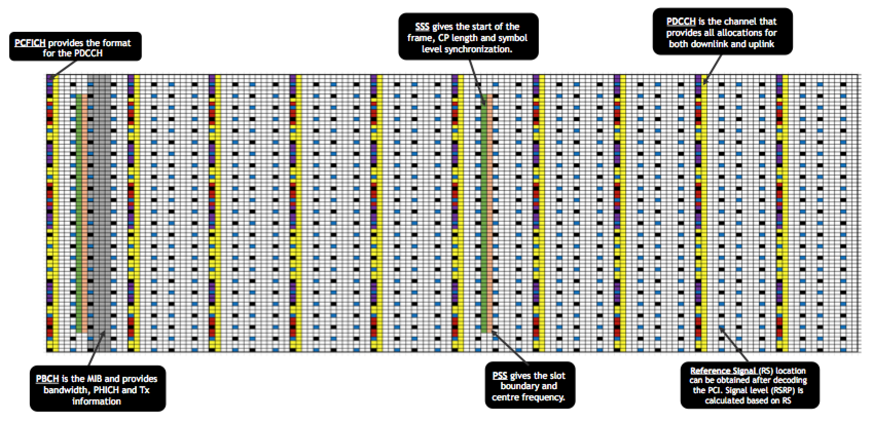
Once, the UE has decoded both the PSS and SSS, it can derive the PCI which tells the location of the RS and the PCFICH. This lets the UE get the RSRP and verify that the cell is above the cell selection threshold. Then it goes for PBCH which is after the PSS of the first subframe. PBCH tells about the system BW, System frame number, PHICH config and number of Tx. Now that the UE knows PHICH, PCFICH and RS location, all the other REs belong to PDCCH.
The UE looks for the DCI for SIB-1 by decoding the DCI masked with CRC of SI-RNTI. The SIB-1 is sent after every 20 ms but the TTI is 80 ms (like PBCH – comes every 10 ms but the TTI is 40 ms). The copies of SIB-1 after 20 ms are different redundacny versions of the same SIB-1. The SIB-1 tells about the other SIBs (SI periodicity and SI Window length), including SIB-2 which tells about the RACH information required for uplink synchronization.
The location of RACH is determined by the following parameters in SIB-2
PRACH CONFIGURATION INDEX ==> Tells the SFN (even/odd) and subframe number – thus the location in time domain
PRACH FREQUENCY OFFSET ==> Tells the PRB offset and thus the location in frequency domain
NCS VALUE ==> Tells the NCS value and the number of root sequences per cell needed to generate 64 preambles
ROOT SEQUENCE INDEX ==> Tells the starting root sequence index for the cell
Based on these values, the UE generates a random preamble and sends a RACH request. After the RACH request, the UE needs to start reading PDCCH for its RA-RNTI after 3 subframes (3 SF after the prach preamble transmission is finished). The RA RSP WINDOW SIZE tells the maximum number of subframes within which the eNB needs to send the RAR. Usually, it is set to 10 SF and therefore the eNB needs to respond to a PRACH request within 12 SF. The RAR contains RA-RNTI or temporary C-RNTI and RAPID (which contains the preamble ID that UE sent).
Once RAR is received, the UE sends msg3 which is RRC Conn Req message that contains UE ID (TMSI or random value). eNB responds with a MCE Contention resolution message before RRC Conn Setup and that contention resolution message contains the same UE ID that is sent by UE in RRC Conn Req message. So, if there are two UEs using the same preamble, then at this step the contention will be resolved. As the UE with the same ID will send the HARQ ACK to Contention resolution message but the other UE will consider RACH failure and re-initiate RACH. In response to RRC Connection Request, eNB sends a RRC Connection Setup which carries SRB1 (Signalling Radio Bearer) addition parameters. Before this, the UE uses SRB0 to send the RRC message.
Once the UE gets RRC Connection Setup message, the UE responds with the RRC Setup Complete message. It is this message that carries NAS messages. At this moment, the RRC setup is completed and SRB1 is also setup.
Based on this, the eNB initiates S1 Initial UE message to the MME and MME can respond to this message in different ways but the most common response is S1 Initial Context Setup Request. This message is considered as the ERAB Setup Request and it usually contains the ERAB-ID and QCI that has to be setup for the UE along with MBR configuration of the bearer.Consequently, the eNB reconfigures UE using RRC Connection Reconfiguration message which contains the addition for SRB2 and DRB (data radio bearer) based on the QCI requirement. eNB also sends Security Mode Command to UE to configure the security context at this stage. Once this is done, the eNB responds to MME with S1 Initial Setup Response and at this point the ERAB Setup is considered successful.
If you have any questions or feedback, simply drop a comment below and I will surely get back to you. Also, if this has been helpful, then please subscribe to our Youtube channel – Our Technology Planet for more exciting stuff and videos.
Ali Khalid
Latest posts by Ali Khalid (see all)
- 5G Coverage Expansion Analysis – Find The Optimal 5G Coverage Threshold For Your Network - November 9, 2024
- 5G Coverage Expansion - November 9, 2024
- 5G SA Cell Search & Network Entry Matrix - July 18, 2023
This is some awesome thinking. Would you be interested to learn more? Come to see my website at UQ6 for content about Domains.
Nice work. Great !!!
Thanks Temesgen 🙂
Hi can you please explain why the position is fixed to 7 and 6 subframe for SSS and PSS ?
Thanks a lot for your wonderful explanation… very clear and neat…… Ali Khalid…….
I have few questions in mind:
1.”UE gets to know the CP length as it has the duration of two consecutive symbols (SSS and PSS) so it can derive whether the eNB is using normal CP or extended CP” Please put some more light in it…(i mean how UE will know which CP is being used)
2.Why PSS is same in both the sub frames while SSS is diff?
3.How ue is synchronized in both frame and symbol level once it reads the SSS.
If UE uses extended CP then symbol length will be longer so when the UE decodes both SSS and PSS so it has information on both the symbols and thus it can know which CP it is.
For point 2, SSS is used to get start of frame and it is defined with m0 and m1 sequences while PSS only has three values.
For point 3, as SSS is different in both subframes, so the UE gets information on frame from SSS and as explained above, since after SSS, the UE gets information for both PSS and SSS together – 2 consecutive symbols – so it gets synchronized at symbol level timing.
nice and lucid..
Hi,
I have one question. when the UE sends RAR, which timer it starts(duration etc), within which it should receive the msg3 from the UE?
* when the enb sends RAR
The RAR carries the uplink grant and the UE needs to send MSG3 in that grant. So, it is not really a timer at the eNB that governs it, it is typical scheduling and if the eNB is unable to decode msg3, the UE will send it again with higher power (configurable) for the number of retransmissions that are defined for MSG3.
Very well written article, Sir. Stay blessed.
Thanks Ahsan 🙂
It’s a very good article and can be understood easily. Great explaination. Actually, I knew that PCI is just for only identification within each cells to avoid interference. Now, I knew clearly PCI stands for what and how they process beyond task.
Thank you so much, sir.
You are welcome 🙂
Thank you rahil great explain
Can you please explain why there is no soft handover in LTE, and what are the pros and cons of hard handover
A soft handover is a lot of overhead as LTE is data intensive. However, there are some features like CoMP and SFN that provide coverage and quality enhancements but their functionality is not exactly as soft handover.
Idle mode ,connected mode,mobility optimization with parameter will help more users
Excellent, Very well explained Bro… Thanks for sharing..
I have two silly doubts,
1. Why PSS is placed after SSS in frame structure, UE should decode PSS first right?
2. Why only 168 SSS… I know it is something related to m0 and m1 sequences, but why exactly?
For the first one, yeah the UE should decode PSS first and SSS is decoded after that. Firstly, the SSS is scrambled with PSS so the UE cannot decode SSS without knowing the PSS. Secondly, the SSS has to be near the PSS in order to ensure coherent detection. If the SSS is far away then the coherent time of the channel may be lesser than the difference between PSS and SSS which means that the channel response will have changed and channel estimation will be impacted.
For second one, the answer is within m0 and m1 length which are of length 31 and their combinations make 168 sequences which are defined in the 3GPP specs.
Good work easy to understand.
Thanks Kamal
Nicely articulated..
Thanks 🙂
“After the RACH request, the UE needs to start reading PDCCH for its RA-RNTI after 3 subframes (3 SF after the prach preamble transmission is finished). The RA RSP WINDOW SIZE tells the maximum number of subframes within which the eNB needs to send the RAR. Usually, it is set to 10 SF and therefore the eNB needs to respond to a PRACH request within 12 SF.”
Can you explain this part ?
Also
“The SIB-1 is sent after every 20 ms but the TTI is 80 ms (like PBCH – comes every 10 ms but the TTI is 40 ms).”
Do you mean it is sent after every 20 ms and duration of transmission is 80ms then after further 20 ms , it is sent again ?
It means that if there is a change in SIB, it will be changed after 80 ms but the SIB is transmitted every 20 ms.
This is the mechanism set for the UE to know if the eNB will respond or not. UE sends the preamble and then waits for the response (RAR). Now the eNB needs to respond within a time limit and if the UE does not get the response within that time limit, the UE will send the preamble again with a higher power considering that the eNB might not have been able to receive or decode the previous preamble. This time limit is usually around 12 milliseconds. I hope this clears your doubts.
I meant to about the 12 SFs part , is it related to “UE needs to start reading PDCCH for its RA-RNTI after 3 subframes (3 SF after the prach preamble transmission is finished). ”
As you wrote “The RA RSP WINDOW SIZE tells the maximum number of subframes within which the eNB needs to send the RAR. Usually, it is set to 10 SF”
RA RSP Window Size is usually 10 SF (10 ms) and UE starts reading PDCCH after 3 sub frames so how time limit became 12 SFs (12 ms)
The first TTI in which the preamble is sent is also included.
My query got deleted
Can you explain how
1. After 3 SFs
2. RA RSP Window Size of 10 ms
3. eNB response within 12 ms
are correlated
Ok i got it
After transmitting the PRACH preamble, the UE searches for a response during the time domain window starts during the third subframe after the preamble, and has a length defined by the response window size which is broadcast in SIB2 or can be signalled to the UE within an RRC Connection Reconfiguration message.
The response window size can be configured as 2,3,4,5,6,7,8 or 10 subframes.
&&&
It means the earliest time when the network can transmit the RACH response is 3 subframe later from the end of RACH Preamble. Then what is the latest time when the network can transmit it ? It is determined by ra-ResponseWindowSize. This window size can be the number between 0 and 10 in the unit of subframes. This means that the maximum time difference between the end of RACH preamble and RACH Response is only 12 subframes (12 ms) which is pretty tight timing requirement.
Good work Ali. Keep it up.
Thanks a lot 🙂
Very helpful article. keep sharing more topics.
Thanks, Ajay.
It is a really good article and helpful.
Thanks, Amal. Pleased to know that it helped.
very interesting research ; good job . I will like to Know if it’s possible to get an image for the practical on the field.
tank’s.
Thanks for taking out time and appreciating, Patrick.
The conventional tools in the field start recording from RACH level. While this information is mostly inferred from the 3GPP specs.
Great work , easy understanding 🙂
Thank you, Habib ur Rehman.
Very good way to write which is easily understandable.
Thanks…
Thanks, Kumar. I am glad it helped.
Smoothly Understood 🙂
Great. Thank you for your feedback.
Very well written Article. These are the foundatiom basics every engineer working on LTE need to understand.
Yes. Thanks, Sohail bhai.
Excellent…Keep writing man..
Thanks, Ashraf. I am glad you liked it.
Excellent written article , very easy to understand !
Thank you, Stanley.
Very well written article. And easy to understand
Thank you, Bilal.
What happens if we have RRC timer expiry ?
If T300 expires, the UE will re-initiate RRC procedure.