
As we are moving towards 5G, the concept of Massive MIMO and beamforming are getting much more attention. Like any other Access Technology, there are two aspects to this – capacity and coverage. The essence of Massive MIMO is the massive increase in transmit antenna elements on the gNB. This can increase capacity by increasing the number of MIMO layers or it can improve coverage by using beamforming. Let’s have a look how it is actually materialized in the field.
The concept of Massive MIMO and Beamforming has been explained on various platforms but I feel that the topic is made over-complicated. So, I will try to make it simple such that it can be easily understood.
5G Massive MIMO Made Simple
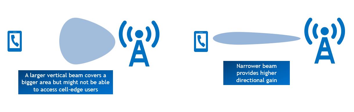
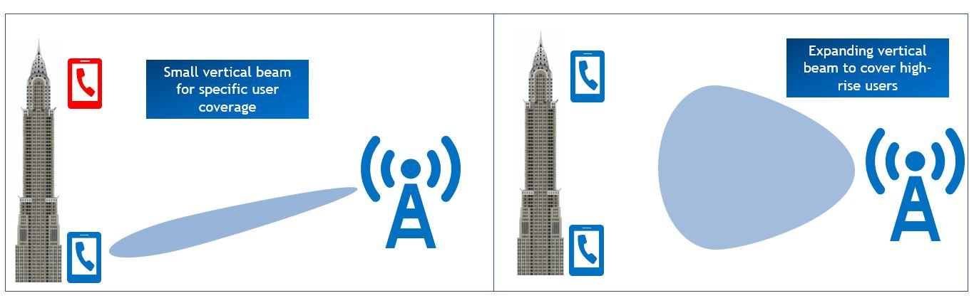
An antenna has a vertical beamwidth and a horizontal beamwidth. If the vertical beamwidth is huge, then the horizontal beamwidth will be reduced and vice versa. In basic beamforming or Massive MIMO, the gNB can reduce or increase the beamwidth along with the direction of the beam. The addition of extra transmit antenna elements increase the accuracy of the beamforming.
The next thing is that most of the beamforming discussions revolve around TDD rather than FDD. This is because of the channel reciprocity. The choice of beam is very important in the beamforming and this needs information from the UE’s end. The algorithm to make this decision is basically based on the SRS in uplink. Since, in TDD, both the UE and gNB will be using the same frequency so the gNB can use the uplink channel to ascertain the downlink channel’s characteristics. However, in FDD, this is extremely difficitult to materialize since the uplink frequency is different than downlink and the characteristics of the channel will not be consistent. So, it is easier to make downlink judgements based on uplink feedback in TDD and therefore, initially the 5G beamforming and Massive MIMO are being deployed in a TDD scenario.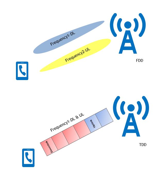 During access, the UE needs to read the SSB (PSS, SSS and PBCH Block) to initiate the network entry. The SSB is sent multiple times and the retransmissions depend on the carrier frequency. For instance, if the SCS (Sub-Carrier Spacing) is 15 kHz and carrier frequency is less than 3GHz then SSB will be situated at {2,8} + 14n where n is set to 0 and 1.
So putting n = 0,
The first SSB will be at symbol 2 and since SSB spans over 4 symbols so it will end on symbol 5.
The second SSB will be at symbol 8 and will cover up to 11.
So putting n = 1,
This gives the location of the third SSB which will start at symbol 16 (2 +14*1)
The fourth SSB will naturally start symbol 22. Both third and fourth SSBs are in the next consecutive slot.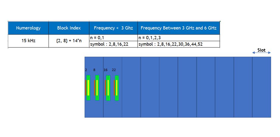 For higher carriers, the value of “n” can increase further resulting in more SSB iterations and thus improve the SSB link budget.
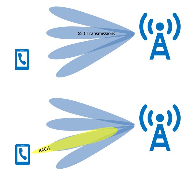
Consider a scenario, where the gNB sends the SSB on different beams. The UE will decode all the SSBs on all the beams and will assign a score to each based on the decoding capability of the channel. So, if the UE finds out that the beam-3 is the best beam so it will only send the RACH in that beam. This way, the gNB will know that this UE chose beam-3 and that will be the best beam to transmit to this specific UE.
Once the UE is connected and data is scheduled, the gNB needs a more dynamic algorithm to choose the best beam for the UE. This is done by either using the SRS from the uplink channel or the PMI feedback from the UE which is a notification of downlink channel response. The gNB prepares a weight matrix for each antenna to ensure that the beam is directed towards the specific UE. Once again, it is difficult to visualize this so let me put it in a simpler way. If the same signal is sent out by all the transmit antenna elements then as each antenna element is separated in space so the output signal will undergo different phase shift or will have different characteristics. However, if the UE can tell the gNB about this difference, the gNB can change the phase and amplitude in advance to counter this effect of the channel. This phase and amplitude shift that is done in advance can be simply said as the weight matrix for beamforming. This can effectively increase the gain and change the direction of the beam. The improvement can be observed by the users that are in null locations (between two beams), cell edge users or users at higher heights for instance high-rise buildings.
Increasing the number of transmit antenna elements will increase the gain for both diversity and beamforming. Theoretically, an Ax1 antenna system provides a gain of 10log(A) dB gain compared to a 1×1 system. As 5G will be using higher end of the spectrum (mmWave in GHz band), the coverage will be a big issue and thus, increasing the number of transmit antennas will increase the gain and counter the higher propagation losses for this band. Therefore, Massive MIMO implementation is more of a compulsion for 5G NR mmWave deployments.
In the next article, I will cover the MU-MIMO and SU-MIMO enhancement introduced by Massive MIMO implementations. In case of any queries or feedback, please drop a comment below and I would love to respond and help. Also, if this has been helpful, then please subscribe to our Youtube channel – Our Technology Planet for more exciting stuff and videos.
Ali Khalid
Latest posts by Ali Khalid (see all)
- 5G Coverage Expansion Analysis – Find The Optimal 5G Coverage Threshold For Your Network - November 9, 2024
- 5G Coverage Expansion - November 9, 2024
- 5G SA Cell Search & Network Entry Matrix - July 18, 2023
Thanks Mr.Ali. Explained nice.
I would like to add few observations as you mentioned the phase shifts for several Beam Ids and amplitudes for different beam ids are informed to the gNB. In LTE I feel same technique is used as complex conjugation techniques for accommodating the delay and repositioning of UE. The local oscillator manages the shifts by harmonizing the Phase samples. A . Transmitter adds an imaginary constants with the in phase value as a quadruple component to every subcarrier while attenuated with IF before LPF. Same technique is applied in RF Carrier multiplexing at HPF. Receiver side has to process the data and reverse mechanism applied to get the original bit stream by demuxing the Components. May be in Beamforming only the no of added Antenna Element could flatten the harmonization and limit the Error vector Magnitude at the Oscillator Path. And at the same time No of increased antenna elements can lead to a higher gain at obvious rate . The RMS error limitation and EVM Limitation technique is same as in OFDM.In LTE bit resolution is lesser as compared to 5G(No of Antenna Array Elements)
Please share the article on SU-MIMO and MU-MIMO as mentioned.
Thank you very much Ali Ji, for sharing such a simplified explanation,It is very valuable info to us,
You are welcome 🙂
Thanks Ali. When will you have the su mimo and mu mimio ready.
Thank you Mr.Khalid for nice explanation..
Regarding the SSB periodicity, in the spec its mentioned that for initial cell selection, SSB occurs with a periodicity of 2 frames. just wondering how did arrive to this value and if possible to change to higher/lower value and its effects.
Could you please provide your inputs on this. Thank you very much!
Explained really well!!!Looking forward for more.
Hi Mr. Khalid, Nicely explained.
I have few questions
1. Differentiation of best beam by UE (on what basis)?
2. When multiple beams are transmitted by gNB, then the beam not chosen by UE, that will be waste of Signal, am I right?
3. SSB calculation is not clear to me, Can you please share some doc. for brief explanation?
4. Is the Beam forming is differentiated in 2 categories like small vertical and Expanding vertical beam? if yes, then what is that multiple beam scenario?
Would be happy for your reply!!
The UE can differentiate between beams based on the different reference signals for each beam. The initial beamsweeping is for access so it has to be done as the gNB does not know when and where the UE will initiate access. The SSB details can be read under 3GPP document (38000 series). Normal beamforming or 2D beamforming works in horizontal plane. But 3D Beamforming adds vertical plane adjustment as well.
Thank you khalid. Very well explained.
How does the Ue differentiate multiple beams of one antenna in UL? Do these beams have different SSBs?
Or let me ask the question in another way:
Does each cell have one single SSB or each beam of one cell will be serving in different SSBs?
The SSB is effectively same but the reference signals embedded inside each SSB will be different providing a mechanism to UE to differentiate between them.
Hi Ali Khalid,
Can you provide pdf or something related to 5G whole thing?
Thanks in Advance
I will share once it is finalized
Very well said Khalid, generous illustrative diagrams and we are growing closer to 5G.
Thanks Terrence
Thank you so much for such precise explanation…Thank you!
You are most welcome
there are still FCC power limits that beamforming can’t exceed. what it does do though is provide a lower noise floor and less noise pollution which helps with capacity and throughput.
Yeah ofcourse, the power limits cannot be exceeded.
Thanks for such a nice explanation.!
You are most welcome 🙂
Thanks for this info. One small question.
You said: “if the UE finds out that the beam-3 is the best beam so it will only send the RACH in that beam”. How does UE differentiate between beams and how it will reply back that beam number? From what I understand a beam is different from another one because is propagated in different direction and arrives at UE with different path loss.
Hi Khalid,
Nice article. I think for frequency between 3 and 6GHz, the last symbols is 50 and not 52. If less than 3GHz, (ie, LTE frequency) is used for 5G, how is 5G cell deployment look like? is it equivalent to a single beam and cell have only single SSB ?
Thanks man , really nice and simple explanation.
Thanks Saeed 🙂
very well explained.Please share some notes/essence about mMIMO usage in exiting LTE Networks ( as trials being done every where across the globe) also share some article on 5G NR Protocol stack.