
This is the first part in LTE KPI Optimization and more related articles will be published soon. So, let us get started without wasting any further time.
LTE KPI Optimization – RRC Success Rate
In LTE KPI Optimization series, this session explains the LTE RRC Success Rate KPI. The session covers the signalling flow for LTE accessibility in detail along with messages where the KPIs are pegged. The causes of LTE RRC failures are also covered in detail along with actions that can resolve those issues.
When the UE wants to attach or connect to the network, it needs to setup a RRC Connection as explained in my article LTE Network Entry Steps. But before that it needs to get synchronized in uplink. This is done by sending a RACH preamble (Msg1) to the eNB and eNB responds with a Random Access Response (RAR aka Msg2). This is where the UE sends a Msg3 also known as the RRC Connection Request and this marks the attempt for the RRC Success Rate KPI. This message contains the objective of the connection and based on that it is subdivided into following major categories:
- Mo-data : Usually used for UE coming back from idle mode if it has data to send or if it has to make a call
- Mo-signaling : Most commonly observed for TAUs and Attach messages
- Mt-access : Idle UE responds to a paging message
- Emergency
- High Priority Access
It also contains a UE identity which can be a TMSI value if the UE was already previously attached to LTE and had a TMSI allocation or it can be a random value indicating that the UE does not know about its TMSI or it might be coming from another RAT.
Based on this request, the eNB sends a RRC Connection Setup message which contains the information of SRB and some basic radio parameters like power control, SRI & CQI periodicity.
Once, the UE gets the RRC Connection Setup, it makes the changes based on the instructions in the message and then responds with RRC Connection Setup Complete message. This message also contains the NAS information if the UE intends to send it.
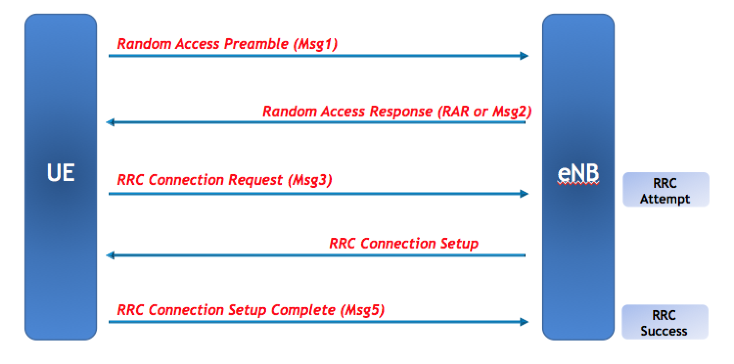
The eNB pegs RRC attempt counter when it receives the RRC Connection Request and the process is deemed successful on the receipt of the RRC Connection Setup Complete message.
Common Failures In RRC Setup Phase
In order to maintain and optimize the RRC KPI, one should know the major issues that can cause a RRC setup failure.
RRC Setup Failure Due To No Response
This is the most common RRC failure which is present in every network. Most of the failures in the RRC stage are due to no response from the UE. This means that the eNB receives RRC Connection Request message from the UE and responds with a RRC Connection Setup message but does not receive or is unable to decode the RRC Connection Setup Complete message.
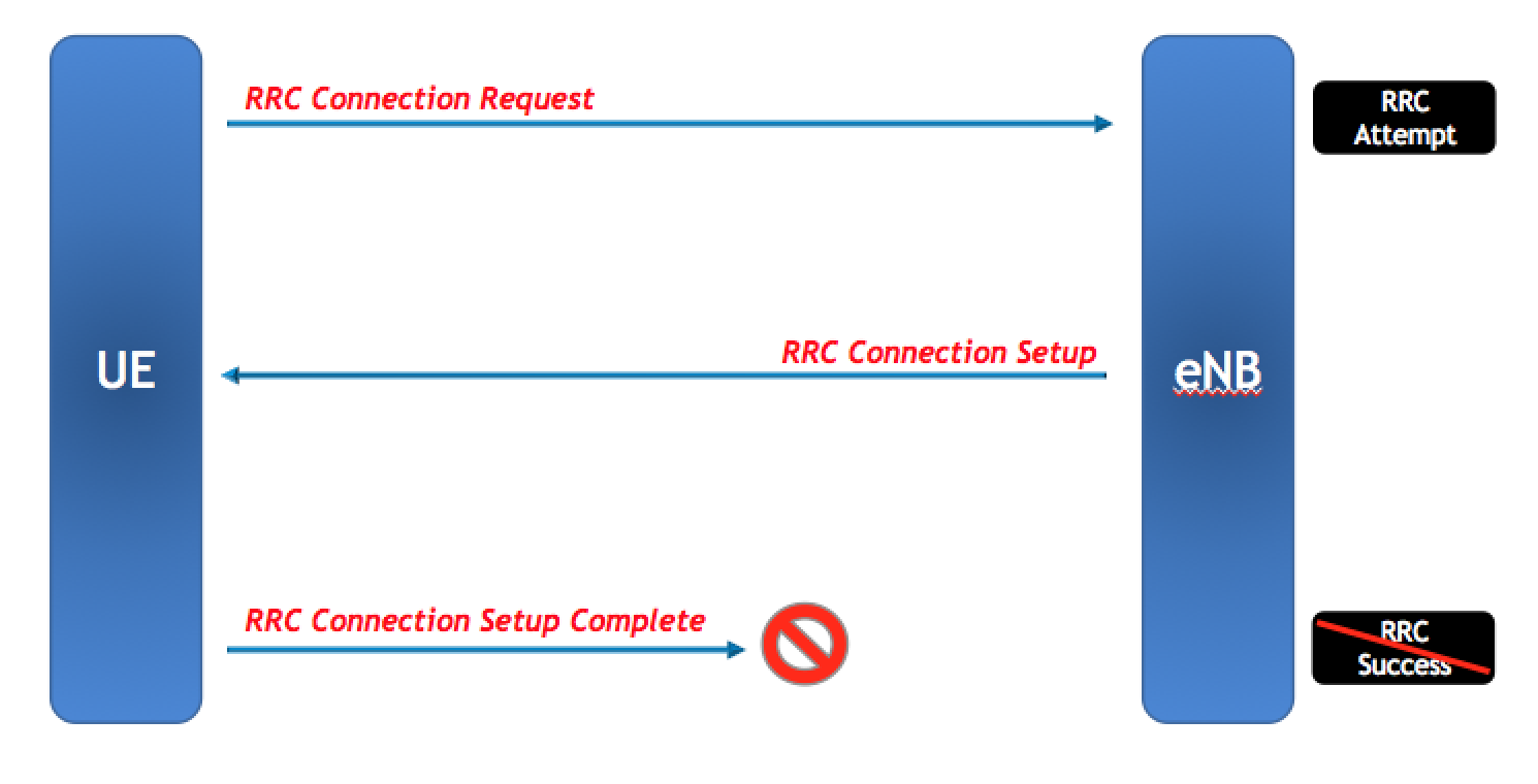
Now let’s understand why this happens. The RRC Connection message is usually around 7 bytes in length while the RRC Connection Setup Complete message may contain the whole NAS information (like TAU or Attach Request) and its size can vary from as small as 8 bytes to as big as over 100 bytes. Consider that a UE near cell edge with limited power sends a RRC Connection Request. Since, it is only around 7 bytes, it will need a small number of RBs so power per carrier will be high. But when it needs to send RRC Connection Setup Complete which is around 100 bytes, it will need a bigger number of resources even if the message is fragmented. So, the average power per carrier will be reduced leading to a higher probability that the message may not be decoded at the eNB.
This can also happen if there is interference on the cell as it will make it further difficult for the eNB to decode the message. It can also happen if the UE fails to decode RRC Connection Setup message so it will never send the RRC Connection Setup Complete message.
RRC Rejections
This is the second issue that can happen but it is usually much less observed in commercial networks compared to the failures due to no response. In these cases, the eNB rejects the incoming RRC Connection Request by sending a RRC Reject message. This is mostly observed when eNB experiences congestion and there are not enough resources left to assign to a new user requesting a RRC Connection.
If the PUCCH is congested, the RRC connection can be rejected. PUCCH carries HARQ ACK/NACKs, CQI and SRIs. If the PUCCH resources are not available, users will not be able to send CQIs and the eNB cannot schedule without CQI information. Usually vendors implement PUCCH in a way that when PUCCH utilization is increased, the CQI interval is increased. For example, users sending CQI with an interval of 10ms will be shifted towards 40ms in order to increase the capacity of the PUCCH.
But when no further capacity is available, the eNB needs to put a limit on new incoming connections resulting in RRC Rejections. Similarly, RRC Rejections can be seen if the active UE count increases beyond the board limit or if the CAPS exceed the limit. The details related to troubleshooting and optimizations for such issues is given below.
Optimization For RRC Success Rate KPI
The following procedures are usually used based on different scenarios
Conventional Method : Physical Optimization
The easiest and conventional method is the physical optimization. For instance, down-tilting a cell will reduce the coverage and remove the far-away users. This will reduce the probability of RRC failure due to no response. However, there will be issues that might not be resolved by the conventional approach so I have listed down other methods that might come in handy.
Relevant Timers
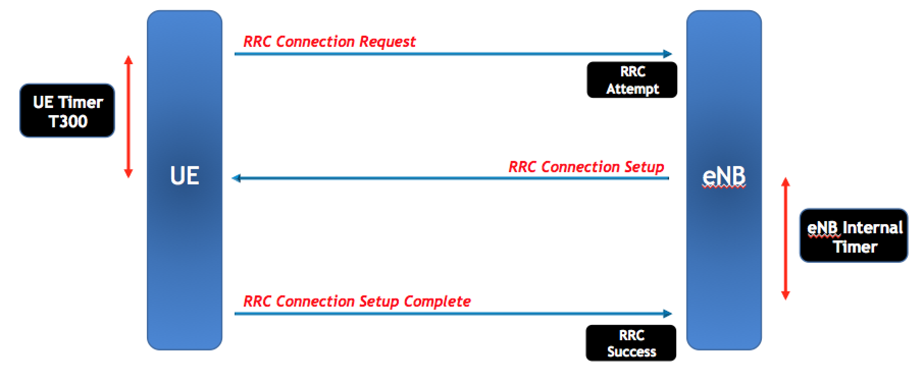
There are two relevant timers for RRC Success Rate KPI.
The first timer is maintained on the UE and it is the famous T300. UE starts it after sending the RRC Connection Request and stops it at the receipt of RRC Connection Setup or Reject message. If this timer is too small, the UE will stop waiting for the RRC Connection Setup message and the RRC procedure will fail. So, increasing this timer can help in this phase.
Secondly, eNB has an internal timer (different vendors have different names for it) which the eNB starts after sending the RRC Connection Setup message. It stops this timer after successfully receiving the RRC Connection Setup Complete message. So, if this timer is small and the UE is trying to send the RRC Connection Setup Complete with retransmissions, then the eNB will consider it a failure as soon as the timer expires. So, increasing this timer might also help in certain scenarios.
Coverage Enhancement & Power Control
The RRC failures due to lack of response from UE can also be caused if the power control on the PUSCH is not correct or if it is too conservative. For instance, the power control on PUSCH depends on the P0 Nominal value as well as Alpha factor. Different vendors use different settings here like using a low P0 Nominal value (for example -100 dBm) with a higher Alpha factor of around 0.9 or 1 or a using a high P0 Nominal value (for example -70dBm) with a smaller Alpha factor of 0.7 or 0.8. But if both the P0 Nominal and Alpha factor are low then the UE will use a smaller power value to send the RRC Connection Setup Complete and therefore, the chances are that it will not be decoded correctly.
In case there is interference on the cell, then features which mitigate interference should be enabled. For instance, enabling Interference Rejection Combining can provide good gains in such scenarios.
Mobile Originating Signalling RRC Success Rate
Usually Mo-Sig RRC Success Rate is lower than others. The reason is once again linked to the size of the MSG-5 (RRC Connection Setup Complete). For a normal Mo-data or Mt-access, the size of RRC Connection Setup Complete message is around 8 to 10 bytes but for Mo-signalling, it can vary and usually is above 50 bytes. This is because Mo-signalling RRC Request is usually used for NAS signalling messages like Attach Request or Tracking Area Update Requests. These messages are big in size and are sent inside the RRC Connection Setup Complete message as NAS. So, this reduces the RRC Success Rate of RRC Mo-Signalling compared to other RRC Request types.
This means that if the network has a higher ratio of RRC Mo-Signalling requests then it will have a lower RRC Success Rate. Usually, Mo-Signalling is around 20 to 25% while Mo-data has the highest percentage. Still it can vary from network to network based on TAC planning and mobility strategy. However, if you have very high Mo-Signalling percentage then the chances are that RRC Success Rate will be relatively lower compared to another similar network with lower Mo-Signalling percentage.
Incompatible UEs
It has been seen that sometimes there are users that are not compatible with the configuration of the network. So, once they receive the RRC Connection Setup message and they find out that they are not compatible with the configuration provided, they do not respond with a RRC Connection Setup Complete message resulting in a RRC failure on the eNB. However, such users keep trying again and again impacting the KPI. This kind of issue can be seen from the traces or CHRs that verifies that it is a single user. It might be inferred from the RRC counters as well since the number of failures are relatively same in consecutive intervals. However, such cases usually go unsolved as it is not a network issue but an abnormal UE problem.
PUCCH Based RRC Rejections
RRC Rejections due to PUCCH congestion can be solved by simply increasing the PUCCH Resource Blocks. Vendors have parameters for PUCCH allocations and minimum PUCCH Resource Block allocation is 4 per subframe. This is because each slot has PUCCH RB allocation on both ends of the band so that means that each slot will have atleast 2 Resource Blocks for PUCCH – one at the top of the frequency band and the other at the bottom of the band. Since, each subframe has two slots so that means that the subframe will have atleast 4 PUCCH Resource Blocks.
When 4 PUCCH RBs are not enough, they can be expanded to a higher value using parameter or in some implementations, an adaptive approach can be maintained where the eNB changes the PUCCH RB count dynamically based on the load requirement. This approach solves the issue completely.
User Count Based or Flow Control Based RRC Rejections
Different baseband boards and vendors have different limitations on active user count and CAPS (Call Attempts Per Second). When such limitation is reached, incoming RRC Connection Requests are rejected by the eNB based on flow control or resource issue. In such cases, the following basic steps can be done
- Decrease the UE Inactivity Timer to a smaller value. This will initiate early release for the users and load due to user count will be reduced. However, this can increase the signalling load as idle users can try to come back to network more frequently which can increase CPU usage of the eNB. So, only use this if the issue is related to user limitation while CPU usage is fine.
- T302 should be increased to limit the RRC signalling load. When a UE gets a RRC Reject from eNB, it has to wait for T302 seconds before sending another RRC Connection Request. So, increasing T302 will increase the interval between such RRC Connection Requests and therefore, reduce the signalling load on the eNB.
- Mobility Load Balancing is another feature that can help in such a scenario by moving users away from the congested carrier to another less utilized carrier.
If you have any questions or feedback regarding this article, simply drop a comment below. I will respond accordingly and also intend to write more about KPI Optimization soon. Also, If you liked this article, then please subscribe to our Youtube channel – Our Technology Planet for more exciting stuff and videos.
Ali Khalid
Latest posts by Ali Khalid (see all)
- 5G Coverage Expansion Analysis – Find The Optimal 5G Coverage Threshold For Your Network - November 9, 2024
- 5G Coverage Expansion - November 9, 2024
- 5G SA Cell Search & Network Entry Matrix - July 18, 2023
Thank you for the insights, truly appreciated!!
Office Interior Designer
This article provides a clear and detailed explanation of LTE RRC Success Rate KPI and its significance in network optimization.
The breakdown of signaling flow and causes of failures is particularly insightful. It’s a must-read for telecom professionals looking to enhance LTE accessibility and resolve RRC issues effectively. Looking forward to the next part of this LTE KPI Optimization series!
I know a lot of folks whom I think would really enjoy your content that covers in depth. I just hope you wouldn’t mind if I share your blog to our community. Thanks, and feel free to surf my website Seoranko for content about Wealth Management Solutions.
With your post, your readers, particularly those beginners who are trying to explore this field won’t leave your page empty-handed. Here is mine at Webemail24 I am sure you’ll gain some useful information about Food Delivery too.
This article will help to measure my business success rate and then I will optimize it.
Digital Marketing Institute
IFDA is India’s no 1 Computer Institute. Boost Your Career With IFDA .We provide various govt and non govt IT courses to all the desired students in India
Additionally if a UE misbehaviour is due to a ‘SW error’ and is ‘a source for some kind hacked/attack’, is it possible to handle these in the RAN itself- during registration phase? and take some ‘barring action’?
Thanks for your comment, Arun. Can you please post your question under this video on YouTube (URL below) and Ali Khalid will be able to reply then ?
https://youtu.be/TbgOBoD7cNQ
hi Khalid, its a great article providing some distinct insights. I have a query, for ‘Incompatible UEs handling – how can eNB/gNB identify the ‘same source/UEs’ in repeating ‘RRCSetUp attempts’ and ‘causing a signalling overload’, and then ‘initiate some evasive action’? ; that is if its possible to prevent such UEs from making re attempts in the RAN itself’?
Thanks for your comment, Arun. Can you please post your question under this video on YouTube (URL below) and Ali Khalid will be able to reply then ?
https://youtu.be/TbgOBoD7cNQ
Hi,
I want to learn more about the KPI optimization process, Please guide and if possible share the Full KPI optimization Link.
Thank you for sharing the best!
You may get information on other KPIs on the articles on this website. However we are shifting from articles to video lectures (Youtube) as it seems to be the popular demand. I will try to create a lecture on KPI optimization topic too.
Many thanks for you..
Please, I need to understand more about PDUCCH and Po nominal and alpha, what are these parameters and how can we modify them.
Thanks bro
Hello Mahmoud,
Thank you for your comment.
Please follow the link below and post your question/feedback in Youtube comments section so that Ali Khalid will be able to answer.
LTE RRC Success Rate – https://youtu.be/TbgOBoD7cNQ
This is very useful info.
Then, What message will trigger if authentication failures. (I mean if anything failed after RRC connection setup complete what would happen).
RRC Drop cause some misunderstandings like volte or data drop. As far as I know, RRC drops are Radio Link failures but how we make sure that they are counted on Accessibility or Retainability… Thanks….
If you are referring to abnormal releases then they are counted under retainability.
Excellent post. Thanks for sharing your experience.
Glad to know that it helped 🙂
Ali, do you have VoLTE UL PDCP SDU Packet Loss Opto guideline?
The post is really helpful. Can you please help me understand where we can find these reasons during call log analysis?
Some of them can be seen from counters provided by vendors while for others you will need L3 trace analysis.
thanks Ali, very helpful
Thanks ALi , Missing you so much
Great to hear from you 🙂
Thanks Khalid nice explaination..!!
You are welcome, Kamal
Thanks Khalid Bhai. Excellent Post with detail Explanation.
Thanks Again..Please keep posting.
You are welcome, Sushant 🙂
The size of RRC connection Set Up complete message is too high ( 8 to 100 bytes) when compared to RRC connection Request (7 bytes). The UE at cell edge transmits with full power. As the Later have small size ,less PRB only required. Hence power per carrier will be more and it can easily reach eNB. But for the former the power per carrier will be less as it required more PRB.
some confusion… on this .. The total power will be distributed in all RB na? ( Like for 20MHz , total power distributed over 1200 subcarriers )
The total power is distributed equally for downlink but for uplink each UE does not get the full 1200 SC (20Mhz example). The UE may only get an allocation of 5 PRBs then its power can be distributed among 5 PRBs. So, if the message size is big for uplink, then its power will be distributed on more PRBs reducing the overall power per PRB and the decoding probability at eNB.
Excellent post bhai..video bhi banaye he kya?
Thanks. No video at the moment.
Mashalha Thanks for sharing…!
Glad, it helped 🙂
Please post related ERAB Setup success rate & Call Setup Success rate.
You can go through it on the following link
https://ourtechplanet.com/lte-erab-success-rate/
Hi Ali,
Great post. can you please she some light on possible reasons of S1 Setup Success Rate degradation? I have a cell whose E-RAB SSR is fine but S1 SSR is impacted severely. Can you please suggest what counters to look for or what checks to be done to get to the bottom of it?
S1 failures can be caused due to timeout of response message to S1 Initial UE Message. Check if the S1 timer is set to a small value. Or it can happen if one of the S1 links in a pool have an issue.
Thank you so much!!!
Nicely done, these information you can’t even find them in IEEE
Thanks Baha. That means a lot to me 🙂
Excellent work dear Ali … Keep on sharing these valuable stuff
Thanks Imran 🙂
AOA Ali bhai,
what an excellent work you have done ,that is the stuff i was looking for thank you so much.
ali bhai where are you working now days please.
Thanks Fahim. I am in Oman nowadays 🙂
excellent post, very useful information.
Some questions;
How can we find the incompatible UEs that are impacting the KPIs because they fail in the RRC accesses?
What tools can we use?
Would you know how to approach the problem in Ericsson LTE technology?
Thanks in advance
Thanks Bernardo. A simple way would be to use a RRC trace and check the RRC message. If it is a single UE issue then from RRC trace, inside the RRC connection request, look for its identity. This user will be trying RRC multiple times and failing each time and you can look at the identity to verify it.
Assalamaulaikum wa rahamthullahi wa barkathuhu brother ALI masha allah Excellent articles,Easy to understand
Thanks 🙂
Assalamaulaikum wa rahamthullahi wa barkathuhu brother ALI masha allah Excellent articles,Easy to understand
May allah(swt) increase your knowledge in deen and duniya. AAMEEN
jazakallahukhairan
*Mubeen Hussain Mohammad* From INDIA(Hyderabad)
Hello Sir,
Thank you for your post.
I have one doubt Once UE receives rrc connection reject ue wait for t302 timer before sending rrc connection requet again, what if again rrc connection reject received ?
If again ue send rrc connection request then can you tell me how many time ue can send rrc connection request after failure?
Excellent articles. Easy to understand. Keep writing Ali bhai.
Thanks Ammar.
Hi Ali,
Can you explain more about T302?
Because in my network T300 is the maximum. Therefore only T302 can optimize. How many seconds we can put for maximum for T302? Is there any side effects after changing? Thanks very much and looking forward to your reply.
It is very good Article, with detail explanation. Thanks!!
Please keep posting for further KPIs too.
Thank you sir for your valuable information, which gave me good knowledge in lte kpi troubleshooting… I would like to know more on CSFB, SRVCC, volte KPI troubleshooting tips if possible.
Just published another article on CSFB
https://ourtechplanet.com/csfb-circuit-switch-fall-back-explanation-optimization/
Excellent notes.. Sir.. Really helping me to know about kpi troubleshooting.. Thanks sir..
Sir if possible could you Plz share some knowledge on handover in lte..
Thanks. I will put that in my list 🙂
Nice article.
Could you please share troubleshooting steps for 3G hsupa and hsdpa alarms and RRCSR Issues in nokia flexi Bts .
Thanks Ansari. I try to keep my articles vendor independent 🙂
Nice article.
Could you please share troubleshooting steps for 3G hsupa and hsdpa alarms and RRCSR Issues in nokia tool. Like from BTS manager.
Thanks a lot sir,
nice one, its really helpful.
You are welcome 🙂
i need a solution to improve the Erab Failures in LTE , what parameter retune will improve it in Ericsson system pls help on it
It depends what is the cause of the ERAB failures. Can you share the main cause – RNL, SRB, SMC, MME?
Great and in detail explanation … Thanks Sir
Thanks Khalid,
Thanks for sharing ,it is very useful and easy to understand.
Can u post something on functionality in LTE.
Can you elaborate more – like which functionality are you referring to?
Hello Ali , Nice Article.
When we increased T300 from 200ms to 800ms , we observed that RRC SR enhance ( expected ) , but also there was degradation on RA SR , are you ave any clue?
It should not impact RA SR. Can you share the details so I might be able to help.
yes , it will degrade non-contention based RASR(related to handover)
Can 2 different handsets (different vendor) have same FGI?
FF4FFE9A FGI is observed to be Faulty UE but can it be of any other handset
Can we say FGI is unique wrt one specific handset
Awaiting your kind response
Yeah, FGI just shows the features that the UE supports so it can be similar between different UE types or models.
Dear Ali , Very good initiative sharing is caring above all it will bless you more with goodness and rewards.
Thanks 🙂
Dear Ali.. Very good insight indeed !! Thanks
Very good info
Sir can u plz share some info on paging discard, related parametrs n hi cap parametrs as well
Ok, I will write something on that soon
Thanks for sharing ,it is very useful and easy to understand .
You are welcome 🙂
Thanks so much, so helpful.
You are welcome 🙂
Very Impressive, Outstanding. Keep posting
Very good post, exellent!
Nice Explanation
for the T300 timer, what is the expected disadvantage for increasing it?
also what is the name of eNB internal timer for Huawei?
Increasing T300 can increase access delay and you can find the relevant under enode connection state timers.
Very Nice Explanation…Please Keep on posting…
So all possibilities are there
So “Random Value” under TMSI header in CHR logs analysis via eFMA corresponds to the same “Random Value” you mentioned in your article and it is likely it is single UE issue
Whenever i checked CHR logs , either there is one TMSI or Random Value under which all RRC Setup No Reply (Mo-SIg) Failures are pegging
So i just need to confirm it
Kindly confirm so that this confusion can be cleared regarding Random Value in CHR logs (via eFMA)
If it is same TMSI then definitely it is a singe UE issue. But if you do not have TMSI and the logs show a Random Value then it may or may not be the same UE. You may need to look at the TA information or FGI if that is available.
TA = Timing Advance samples (each TA)?
Yeah Timing Advance value
So if for example TA Index 3 samples are increased from the same time (RRC Failures) then it will point to single UE issue?
And reason would be ?
Secondly FGI ?
Awaiting your kind reply
Yeah if TA value is mostly 3 then it should be a single UE
Another query i have regarding TMSI
For example following TMSI are appearing
FF 3G 81 D7
FF 5K 81 D7
FF 6O 81 D7
Does it correspond to same UE
Plus do you have anything how TMSI is created , any common thing which may hint towards Single UE TMSI
The generation of M-TMSI can vary with vendors. For instance in above case, if the vendor is Huawei, it will be the same user.
Yes , vendor is Huawei
I have witnessed cases in CHR logs where TMSI is similar to e.g FF XX 81 D7 (where XX is random) and increase in TA Index Y has increased mapping with KPI degradation
“it can be a random value indicating that the UE does not know about its TMSI or it might be coming from another RAT.”
Are you referring to the random value which appears in CHR logs when analyzed via eFMA.
Huawei Chinese expert said is likely that it is single UE issue and this UE is accessing the network for the first time
No, when a UE tries to access the LTE network, it has to add an identity in the RRC Request. This is usually TMSI but when the UE is not active for a long time or the UE moves to another RAT and then comes back again after some time, the UE sends a random value in the RRC Request. Then the EPC assigns a new TMSI to this UE. This does not have to be a UE that accesses the network for the first time. Usually you can see this in the Uu or RRC layer logs.
Nicely explained article. Great job and thanks for sharing it.
Thanks Vishal
Great Stuff. Thank you
Thanks 🙂
Excellent work..Keep it up man
Thanks a lot 🙂
Hi Ali,
I’m just curious about this part “eNB has an internal timer (different vendors have different names for it)”
Such as what parameter name is that? Would you like let me know from part vendor Ericsson, Nokia or Huawei?
Thank you 🙂
I am trying to keep this vendor independent but you can get the parameter name from the vendor’s documentation under network access.
Hi Bro
For Nokia– which parameter represent to eNB internal timer?
Thanks
Khan
I am trying to keep this vendor independent 🙂 You should be able to find the timer details in the access related documentation.
T300, T301, T304, T310, T311 among others
Thanks khalid.
Very nicely explained. Keep posting further.. will surely read.
Thanks, Shekhar.
Excellent
Thank you, Sulaiman.
Great!!
Thanks, ALEXANDRINO.
Thanks for sharing great info !!
For vendor specific part if rejection due to number of users can we increase maxnumrrc parameter instead of changing inactivity timer
Usually such a limit is either a license issue or a board capacity issue. So, they are not readily change-able.
Thanks a lot for very informative post which is very easy to understand !!! Request you to keep posting on another LTE KPIs as well. 🙂
Thank you, Tarun. I am glad that it helped.
Thanks for sharing Ali, waiting for more stuff…..
Thanks for your appreciation, Abdullah.
Good one keep writting…
Thanks, Vignesh.
Excellent information and very useful with great explanation which covers whole subject. Thanks Ali Bai. Looking forward for more.
Thanks alot. I will be covering all the important KPIs so keep checking 🙂
Pls share how to improve low clutter cell and standalone cell SSR
Such cell are difficult to tackle as they have pure coverage constraints. Sometimes, making aggressive changes to cell selection criterion and making it easy to reselect can help the KPIs.
@Ali khalid. Brother kindly please also Publish on MOCN( Multi Operator Core Network) / E-UTRAN Sharing.
Ok, I will put in the list
Ali Bhai!
Excellent sharing
Thanks Luqman. I have been thinking about writing for some time so here I am. I will be sharing more in coming days 🙂
Excellent, very clear and easy to understand!
Thank you, Stanley.
excellent post, very useful information.
Thanks, Roberto. Glad to know that it helped.